Open Access (Artykuł w pliku PDF)
Domestically produced spun concrete power poles after more than 30 years of exploitation
dr inż. Jarosław Michałek, Politechnika Wrocławska, Wydział Budownictwa Lądowego i Wodnego
ORCID: 0000-0002-4242-9054
dr inż. Aleksy Łodo
Adres do korespondencji: Ten adres pocztowy jest chroniony przed spamowaniem. Aby go zobaczyć, konieczne jest włączenie w przeglądarce obsługi JavaScript.
DOI: 10.15199/33.2024.02.06
Studium przypadku
Streszczenie. W artykule przedstawiono stan techniczny elektroenergetycznych żerdzi z betonu wirowanego po ponad trzydziestoletniej eksploatacji. Słupy te są jednymi z pierwszych wytworzonych w Polsce w technologii betonu wirowanego na laboratoryjnej linii produkcyjnej zlokalizowanej na terenie Politechniki Wrocławskiej. Na fotografiach przedstawiono istniejące uszkodzenia żerdzi, omówiono je oraz wskazano potencjalne przyczyny.
Słowa kluczowe: beton wirowany; słupy elektroenergetyczne; trwałość konstrukcji.
Abstract. The paper presents the technical condition of spun concrete power poles aftermore than thirty years of exploitation. The poles in question are among the first ones manufactured in Poland using the spun concrete technology on a laboratory production line located at theWroclaw University of Science and Technology. Existing damages to the poles, which are shown in photographs, are discussed and their potential causes are indicated.
Keywords: spun concrete; electricity poles; durability of structures.
Literatura
[1] Łodo A. Historia uruchomienia krajowej produkcji strunobetonowych żerdzi wirowanych. Przegląd Budowlany. 2011; 6: 29 ÷ 34.
[2] Foerster M. Die Fabrikanlage zur Herstellung Stahlbewehrter Schleudermaste der Akt.- Ges. Dyckerhoff und Widmann zu Cossebaude bei Dresden. Berlin. Armierter Beton, Monatsschrift für Theorie und Praxis des Gesamten Betonbaues. FünfterJahrgang, Januar 1912: 26 – 29.
[3] Foerster M. Neues von den Eisenbeton – Schleudermaste. Berlin. Armierter Beton, Monatsschrift für Theorie und Praxis des Gesamten Betonbaues. Neunter Jahrgang. 1916: 214 – 218.
[4] Kliukas R, Jaras A, Lukoševičienė O. Reinforced Spun Concrete Poles – Case Study of Using Chemical Admixtures. Materials. 2020; DOI: 10.3390/ma13020302.
[5] Dilger WH. Improved concrete poles – part 1; Canadian ElectricalAssociation, Montreal 1980.
[6] Dilger WH, Ghali A. Improved technology for spun-cast concrete poles; Canadian Electrical Association, Montreal 1984.
[7] Dittmar F, Bahous H. Spun pre-stressed concrete poles: alternative to wooden and steel poles for low, medium, and high voltage. 21st International Conference on Electricity Distribution, Frankfurt, 6-9 June 2011, Paper 0392.
[8] PN-EN 1992-1-1:2008. Eurokod 2: Projektowanie konstrukcji z betonu. Część 1-1: Reguły ogólne i reguły dla budynków.
[9] PN-EN 206+A2:2021-08. Beton. Wymagania, właściwości, produkcja i zgodność.
[10] Kubiak J, Michałek J, Łodo A. Zabezpieczenie strukturalne i powierzchniowe betonu w słupach elektroenergetycznych i oświetleniowych. Przegląd Budowlany. 2012; 5: 103 ÷ 107.
[11] PN-EN 12843:2008. Prefabrykaty betonowe. Maszty i słupy.
[12] PN-EN 13369:2018-05. Wspólne wymagania dla prefabrykatów z betonu.
[13] Michałek J, Łodo A. Grubość ścianek w strunobetonowych żerdziach wirowanych. Materiały Budowlane. 2017; DOI: 10.15199/33.2017.06.05.
Przyjęto do druku: 02.02.2024 r.
Materiały Budowlane 2/2024, strona 26-29 (spis treści >>)
Open Access (Artykuł w pliku PDF)
Numerical and experimental analysis of the precast concrete slabs reinforced with high grade steel bars with special supporting conditions
dr hab. inż. Maciej Dutkiewicz, prof. PBŚ, Politechnika Bydgoska, Wydział Budownictwa, Architektury i Inżynierii Środowiska
ORCID: 0000-0001-7514-1834
dr inż. Vadim Griniov, Politechnika Bydgoska, Wydział Budownictwa, Architektury i Inżynierii Środowiska
ORCID: 0000-0003-1212-1996
mgr inż. Paweł Majkowski, Politechnika Bydgoska, Wydział Budownictwa, Architektury i Inżynierii Środowiska
ORCID: 0000-0002-2645-9448
Adres do korespondencji: Ten adres pocztowy jest chroniony przed spamowaniem. Aby go zobaczyć, konieczne jest włączenie w przeglądarce obsługi JavaScript.
DOI: 10.15199/33.2024.02.05
Doniesienie naukowe
Streszczenie. W artykule przedstawiono wyniki analiz eksperymentalnych i numerycznych opisujących odpowiedź prefabrykowanych płyt z betonu zbrojonego prętami stalowymi wysokiej wytrzymałości na działanie sił wywołujących zginanie elementu. Przedmiotem badań eksperymentalnych było 45 płyt żelbetowych umiejscowionych na specjalnie przygotowanym stanowisku. Badano wpływ grubości płyt oraz ich stopnia zbrojenia na nośność i odkształcalność elementu. Badano strefę środkową płyty, w której jest stały moment zginający. Stwierdzono, że płyty o grubości 120 mm wykazywały bardziej kruche zniszczenie, podobne do zniszczenia ściskanych elementów betonowych, podczas gdy charakter zniszczenia płyt cienkich 80 mm był bardziej łagodny. W wyniku analiz numerycznych i eksperymentalnych stwierdzono, iż zastosowanie stali B600B pozwala na oszczędniejsze wykorzystanie stali zbrojeniowej. W badaniach eksperymentalnych zastosowano system diagnostyczny pomiaru przemieszczeń i odkształceń, który w łatwy sposób można zaimplementować w warunkach użytkowania rzeczywistej konstrukcji. Uzyskane wyniki eksperymentalne porównano z wynikami z analizy modelu numerycznego.
Słowa kluczowe: odpowiedź na zginanie; płyta żelbetowa; płyta tunelowa; specjalne mocowanie.
Abstract. The paper presents experimental and numerical studies to determine the main characteristics of bent reinforced concrete precast slabs. We tested 45 reinforced concrete slabs with a constant load, in a specially made steel stand. The main purpose of the test is to study the effect of the thickness and percentage of reinforcement of slabs on strength and deformability. The zone of a slab with a constant moment was studied. It was revealed that slabs with a thickness 120 mm showed a more brittle fracture similar to the destruction of compressed concrete elements, while thin plates 80 mm collapsed in a quieter nature. As a result of numerical and experimental analyses, it was found that the use of B600B steel allows for more economical use of reinforcing steel. In the experimental research, a diagnostic systemfor measuring displacements and strains was used, which can be easily implemented in the conditions of use of the real structure. The obtained experimental results were compared with the results obtained from the analysis of the numerical model.
Keywords: bending behavior; reinforced concrete slab; fence slab; special fastening.
Literatura
[1] PN-G-06002:1997. Podziemne wyrobiska korytarzowe i komorowe – Obudowa betonowa monolityczna – Wymagania i badania.
[2] https://helpiks.org/7-9366.html.
[3] Petraroia DN, Mark P. Variable, full-scale tester for tunnel linings. Structural Concrete. 2021; https://doi.org/10.1002/suco.202000806.
[4] Mohammad SH, Erick AB, Rémy DL, Andrés L. High-Strength Steel Bars in Earthquake- Resistant Reinforced Concrete T-Shaped Walls. ACI Structural Journal. 2021; https://doi: 10.14359/51728091.
[5] Chiew SP, Zhao M, Cai Y. Towards the Use of High Strength Steel for Construction Productivity.Australasian Structural Engineering Conference: ASEC 2016. https://hdl. handle.net/10356/80597.
[6] Berger J. Effects of flexural stiffness on constraints of imposed deformations in reinforced concrete structures. Engineering Structures. 2022; https://doi.org/10.1016/j.engstruct. 2022.114973.
[7] Berger J, Pfeiffer M, Feix J. Extended experimental and numerical investigations on constraint forces from imposed deformations. Structural Concrete. 2020; https://doi.org/10.1002/suco. 201900450.
[8] Yi ST, Kim JHJ, Kim JK. Effect of Specimen Sizes on ACI Rectangular Stress Block for Concrete Flexural Members. ACI Structural Journal. 2002, pp. 701-708.
[9] Ibrahim HHH, MacGregor JG. Modification of the ACI Rectangular Stress Block for High- -Strength Concrete.ACI Structural Journal,V. 94, No. 1, January-February 1997, pp. 40-48.
[10] Sakanov КT. Limiting deformations of concrete in elements with a non-rectangular shape of the compressed zone. Science and technology of Kazakhstan №1, 2010. pp. 93-96.
[11] NikulinAI. On clarifying the limiting relative strains of concrete in the compression area of bending reinforced concrete elements Promyshlennoe i grazhdanskoe stroitel’stvo [Industrial and Civil Engineering. 2014, no. 8, pp. 12–15.
[12] Shkurupiy ОA. Ultimate concrete compressibility in reinforced concrete elements. Modern industrial and civil construction. „. 4, N4, 2008, pp. 207-212.
[13] Kim JK, Yi ST, Yang EI. Size Effect on Flexural Compressive Strength of Concrete Specimens. ACI Structural Journal, V. 97, No. 2, March-April 2000, pp. 291-296.
[14] Borges JUA, Subramaniam KV, Weiss WJ, Shah SP, Bittencourt TN. Length Effect on Ductility of Concrete in Uniaxial and Flexural Compression. ACI Structural Journal, V. 101, No. 6, November-December 2004, pp. 765-772.
[15] Repin V, Grinyov V. International Scientific Siberian Transport Forum TransSiberia – 2021. The Experience in Automating Scientific Research to Identify Dangerous Zones in the Near- -Support Sections of Wooden Beams. pp 1230–1238. https://doi.org/10.1007/978-3- 030-96383-5_137.
[16] Program BETA 4.0. PSU. Petsold TМ, Lazowski DN, Gluchow DO.
Przyjęto do druku: 31.01.2024 r.
Materiały Budowlane 2/2024, strona 21-25 (spis treści >>)
Open Access (Artykuł w pliku PDF)
Open Access (Article in English PDF file)
Generalization of Hamilton’s principle for the problem of coupled thermodiffusion
dr inż. Magdalena Sosnowska, Politechnika Bydgoska, Wydział Budownictwa, Architektury i Inżynierii Środowiska
ORCID: 0000-0002-1158-5943
dr inż. Magdalena Lachowicz, Politechnika Bydgoska, Wydział Budownictwa, Architektury i Inżynierii Środowiska
ORCID: 0000-0003-4047-2769
prof. dr hab. inż. Adam Podhorecki, Politechnika Bydgoska, Wydział Budownictwa, Architektury i Inżynierii Środowiska
ORCID: 0000-0002-9569-1769
Adres do korespondencji: Ten adres pocztowy jest chroniony przed spamowaniem. Aby go zobaczyć, konieczne jest włączenie w przeglądarce obsługi JavaScript.
DOI: 10.15199/33.2024.02.04
Oryginalny artykuł naukowy
Streszczenie. Zmienna w czasie temperatura i stężenie substancji dyfundującej powodują deformację ciała stałego. Istnieje również proces odwrotny, czyli odkształcenie ciała stałego powoduje wytworzenie energii cieplnej oraz przepływ masy. Wymienione procesy są ze sobą sprzężone, a badaniem tego sprzężenia zajmuje się termodyfuzja. W artykule rozpatrzono zagadnienie początkowo-brzegowe ośrodka ciągłego, geometrycznie i fizycznie liniowego, przy umiarkowanej zmianie temperatury i stężenia substancji dyfuzyjnej. Zagadnienie takie można opisać za pomocą sprzężonych równań różniczkowych, rozszerzonego równania przewodnictwa cieplnego, rozszerzonego równania dyfuzji i równań teorii sprężystości uzupełnionych o warunki brzegowe i początkowe. W artykule wykazano, że równanie czasopracy wirtualnej, wyprowadzone na bazie równań różniczkowych, prowadzi do uogólnienia zasady Hamiltona. Równania czasopracy wirtualnej i zasady Hamiltona nie da się wyrazić w postaci minimum dobrze zdefiniowanego funkcjonału. Wiadomo, że takie sformułowanie pozwala na zastosowanie metod bezpośrednich. Łatwo wykazać, że z przedstawionej zasady wariacyjnej można wyprowadzić równania sprężystości, przewodnictwa cieplnego i dyfuzji.
Słowa kluczowe: zasada Hamiltona; sprzężona termodyfuzja; mechanika ośrodków ciągłych; termodynamika procesów nieodwracalnych.
Abstract. Variables in time of temperature field and concentration of diffusion substance field cause deformation of the solid. There is also a reverse process, i.e., deformation of the solid causes thermal energy (and its conduction) and mass flow. The mentioned processes are coupled together and thermodiffusion dealswith the study of this coupling. In the paper the problem of initial – boundary of the continuous center with moderate temperature change and moderate change in concentration of diffusion substance was considered. Such an issue can be written with conjugate differential equations, extended thermal, diffusion and the theory of elasticity equations supplemented with boundary and initial conditions. It is possible to described such an issue by the integral form using for this purpose the above differential equations and the equation of a virtual power in the space–time domain. It has been shown in the work that the equation of a virtual power, derived from the above differential equations, actually leads to the generalized Hamilton’s principle. The equation of a virtual power and Hamilton’s principle in the form shown in the work cannot be expressed as aminimumof awell-defined functional. It is known, that such formulation allows the use of direct methods. It is easy to showthat the elasticity, thermal conductivity and diffusion equations can be obtained from the presented variation principle.
Keywords: Hamilton’s principle; coupled thermodiffusion; mechanics of continuous medium; thermodynamics of irreversible processes.
Literatura
[1] Kleiber M. Mechanika techniczna, tom XI, Komputerowe metody mechaniki ciał stałych, PWN, Warszawa 1995.
[2] Podhorecki A. Podstawy teoretyczne metody elementów czasoprzestrzennych, Wydawnictwo Uczelniane Akademii Techniczno-Rolniczej w Bydgoszczy, Bydgoszcz 2005.
[3] He J.-H. Hamilton’s principle for dynamical elasticity, Applied Mathematics Letter 2017; 72: 65 – 69.
[4] Kim J. Extended framework of Hamilton’s principle for thermoelastic continua, Computers & Mathematics with Applications. 2017; 73: 1505 – 1523.
[5] Kim J, Dargush GF. Lee HS. Extended framework of Hamilton’s principle in heat diffusion, International Journal of Mechanical Sciences. 2016; 114: 166 – 176.
[6] Marin M, Carrera E, Vlase S. An extension of the Hamilton variational principle for piezoelectric bodies with dipolar structure, Mechanics of Advanced Materials and Structures. 2023; 30: 2453 – 2457.
[7] Junker P, Balzani D. An extended Hamilton principle as unifying theory for coupled problems and dissipative microstructure evolution. Continuum Mech. Thermodyn. 2021; https://doi.org/10.1007/s00161-021- 01017-z.
[8] Fung YC. Podstawy mechaniki ciała stałego, PWN, Warszawa 1969.
[9] Nowacki W. Termosprężystość, Zakład Narodowy Imienia Ossolińskich Wydawnictwo Polskiej Akademii Nauk, Wrocław – Warszawa – Kraków – Gdańsk 1972.
[10] Nowacki W, Olesiak ZS. Termodyfuzja w ciałach stałych, PWN, Warszawa 1991.
[11] Kączkowski Z. Metoda elementów czasoprzestrzennych, Komputerowe metody mechaniki ciał stałych, PWN, Warszawa 1995.
Przyjęto do druku: 24.01.2024 r.
Materiały Budowlane 2/2024, strona 17-20 (spis treści >>)
Open Access (Artykuł w pliku PDF)
Open Access (Article in English PDF file)
Consideration of foundation stiffness in the design of slender reinforced concrete columns in single-story frame structures
dr inż. Krzysztof Klempka, Uniwersytet Warmińsko-Mazurski w Olsztynie, Wydział Geoinżynierii
ORCID: 0000-0002-5144-6681
dr inż. Ireneusz Dyka, Uniwersytet Warmińsko-Mazurski w Olsztynie, Wydział Geoinżynierii
ORCID: 0000-0002-0996-264X
Adres do korespondencji: Ten adres pocztowy jest chroniony przed spamowaniem. Aby go zobaczyć, konieczne jest włączenie w przeglądarce obsługi JavaScript.
DOI: 10.15199/33.2024.02.03
Oryginalny artykuł naukowy
Streszczenie. W projektowaniu konstrukcji parterowych hal istotne jest uwględnienie sztywności posadowienia, która wpływa na wartość momentów zginających w słupach. W artykule przedstawiono metodę i przykłady obliczeń drugiego rzędu uwzględniające wpływ sztywności podpory na rozkład momentów zginających w słupach wspartych na stopach oraz palach fundamentowych. Przedstawiona metoda pozwala na bardziej precyzyjne, bezpieczne i optymalne projektowanie smukłych słupów żelbetowych.
Słowa kluczowe: smukły słup żelbetowy; efekty drugiego rzędu; sztywność posadowienia; fundament palowy.
Abstract. In the design of single-story frame structures, it is important to consider the foundation stiffness, which affects the value of bending moments in columns. The article presents a method and examples of second-order calculations that take into account the effect of support stiffness on the distribution of bending moments in columns supported on footings and foundation piles. The presented method allows more precise, safe and optimal design of slender reinforced concrete columns.
Keywords: slender reinforced concrete column; second-order effects; foundation stiffness; pile foundation.
Literatura
[1] Eurocode 2: Design of Concrete Structures. Part 1-1. General Rules and Rules for Buildings. EN 1992-1-1:2008.
[2] Klempka K, Knauff M. Design of slender RC columns according to Eurocode and polish code compared with the improved numerical model.Archives of Civil Engineering, 2005; 1.
[3] Pędziwiatr J, Musiał M. Calculation of second- -order effects in columns – applications and examples. Archives of Civil Engineering, 2023; DOI: 10.24425/ace. 2023.144173.
[4] Hamed E, Lai C. Geometrically and materially nonlinear creep behaviour of reinforced concrete columns. Structures. 2016; 5, 1 – 12.
[5] Gilbert RI, Ranzi G. In-service deformations of reinforced concrete columns in biaxial bending. Proceedings of the Twelfth EastAsia-Pacific Conference on Structural Engineering and Construction,Hong Kong, China, 26–28 January 2011, pp. 410-418.
[6] Kim CS, Gong Y, Zhang X, Hwang HJ. Experimental study on long-term behavior of RC columns subjected to sustained eccentric load. Adv. Concr. Constr. 2020; 9, 289–299.
[7] Knauff M. Obliczanie konstrukcji żelbetowych wg Eurokodu 2, Wydawnictwo Naukowe PWN, 2012.
[8] Knauff M, Klempka K. Effective lengths of reinforced concrete columns in single-storey frame structures in the light of the Eurocode. Technical Sciences No 12, str. 71-82, 2009.
[9] Knauff M, Klempka K. Projektowanie smukłych słupów żelbetowych według Eurokodu 2. Inżynieria i Budownictwo. 2009; 12: 663 – 665.
[10] Gorbunow-Posadow MT. Obliczanie konstrukcji na podłożu sprężystym. Budownictwo i Architektura, Warszawa 1956.
[11] Lewiński P. Analiza współpracy żelbetowych zbiorników cylindrycznych z podłożem. ITB, Warszawa 2007.
[12] Coyle HM, Reese LC. Load transfer for axially loaded piles in clay. J. Soil Mech. Found. Div. 1966, 92: 1 – 26.
[13] VijayvergiyaVN, Focht JA. Anew way to predict the capacity of piles in clay. Proceeding of the 4-th Annual Offshore Technology Conference, Houston, TX, USA, 2-5 May 1977.
[14] Randolph MF, Wroth CP. Analysis of deformation of vertically loaded piles. J. Geotech. Eng. Div. 1978, 104: 1465 – 1488.
[15] Kraft LM, Ray RP, Kagawa T. Theoretical t-z curves. J. Geotech. Eng. Div. 1981, 107: 1543 – 1561.
[16] Guo WD, Randolph MF. Rationality of load transfer approach for pile analysis. Computers and Geotechnics. 1998; 23: 85 – 112.
[17] Zhu H, Chang MF. Load transfer curves along bored piles considering modulus degradation. J. Geotech. Geoenviron. Eng. 2002; 128 (9): 764–774.
[18] Lu Q, Luo Q. A Load Transfer Approach for Studying the Load-Deformation Response of Vertically Loaded Single Pile. Proceedings of the 2nd International Symposium onAsia Urban GeoEngineering, 2018; Springer Series in Geomechanics and Geoengineering, pp. 369-384, https://doi. org/10.1007/978-981-10-6632-0_29.
[19] Bateman AH, Crispin JJ, Vardanega PJ, MylonakisGE. Theoretical t -z Curves forAxially Loaded Piles. J. Geotech. Geoenviron. Eng. 2022, 148, 04022052.
[20] Dyka I. Analiza i metoda obliczeń osiadania grupy pali. Praca doktorska, Politechnika Gdańska, czerwiec 2001.
[21] Randolph MF. Science and empiricism in pile foundation design. Geotechnique, 2003; 53(10): 847 – 875.
[22] Poulos HG. Pile Group Settlement Estimation – Research to Practice. Foundation Analysis and Design: Innovative Methods (GSP 153). Proceedings of Sessions of GeoShanghai 2006.
[23] Mandolini A, Russo G, Viggiani C. Pile foundations: Experimental investigations, analysis and design. Proc. of 16th international Conference of Soil Mechanics & Geotechnical Engineering, Osaka, Japan, 12-16 September 2005.
[24] Chow YK. Analysis of Vertically Loaded Pile Groups. International Journal for Numerical andAnalyticalMethods in Geomechanics. 1986; Vol. 10, pp. 59 – 72.
[25] Dyka I. Use of the laboratory tests of soil modulus in modelling pile behaviour. Studia Geotechnica et Mechanica, 2012, Vol. XXXIV, No. 3 (2012).
[26] Srokosz P, Dyka I, Bujko M. Interpretation of shear modulus degradation tests. Studia Geotechnica et Mechanica. 2018; Vol. XXXX, No. 2 (2018), str. 125-132, DOI: 10.2478/sgem-2018-0015.
[27] Fahey M, Carter JP. A finite element study of the pressuremeter test in sand using nonlinear elastic plastic model. Canadian Geotechnical Journal. 1993; 30: 348–362.
[28] Van ImpeWF, De Clercq Y. A Piled Raft InteractionModel. Proc. of 5-th International Conference and Exhibition on Piling and Deep Foundations – DFI’94, Bruges, Belgium, 13-15 June 1994.
[29] Bustamante M, Gianaselli L. Pile bearing capacity prediction by means of static penetrometer CPT. Proceedings of 2nd European Symposium on Penetration Testing, ESOPT – II, Amsterdam, 1982.
[30] Mayne PW, Rix G. J. Gmax-qc relationships for clays. Geotechnical Testing Journal. 1993; 16 (1): 54 – 60.
[31] Gwizdała K, Stęczniewski M, Dyka I. Wykorzystanie sondowań statycznych do obliczeń nośności i osiadań pali. Materiały seminarium „Fundamenty palowe 2009”. NOT Warszawa, 22 kwietnia 2009 r.
Przyjęto do druku: 18.01.2024 r.
Materiały Budowlane 2/2024, strona 11-16 (spis treści >>)
Open Access (Artykuł w pliku PDF)
Short-term creep test of shear adhesive joints in Timber-Concrete Composites
mgr inż. Klaudia Śliwa-Wieczorek, Politechnika Krakowska, Wydział Inżynierii Lądowej
ORCID: 0000-0002-4148-1491
dr hab. inż. Wit Derkowski, prof. PK, Politechnika Krakowska, Wydział Inżynierii Lądowej
ORCID: 0000-0001-6133-3624
dr inż. Eva Binder, Linnaeus University, Växjö, Sweden
ORCID: 0000-0002-5699-4492
Adres do korespondencji: Ten adres pocztowy jest chroniony przed spamowaniem. Aby go zobaczyć, konieczne jest włączenie w przeglądarce obsługi JavaScript.
DOI: 10.15199/33.2024.02.02
Oryginalny artykuł naukowy
Streszczenie. W artykule przedstawiono wyniki badań krótkotrwałych i reologicznych przyrostu odkształceń w teście wypychania (push-out test) w przypadku dwuzakładkowych połączeń klejonych. Łącznie przebadano 15 próbek złożonych z elementów wykonanych z drewna klejonego krzyżowo (CLT) oraz prefabrykowanych płyt betonowych. Połączenie między elementami wykonano jako klejone z użyciem innowacyjnych prefabrykowanych złączy podatnych o grubości 3 mm, w trzech konfiguracjach powierzchni klejenia. Celem badań było określenie wpływu geometrii połączenia klejonego na początkowy przyrost odkształceń w czasie. Wykazano, że pełzanie przebiega nieliniowo w czasie t1 = 800 s niezależnie od powierzchni klejenia, a następnie zwiększa się w sposób liniowy. W przeprowadzonych badaniach złączy pasmowych uzyskano przyrost początkowego pełzania o ok. 10% mniejszy w przypadku złączy ułożonych w kierunku obciążenia niż w kierunku prostopadłym. Wykazano również, że wartości pełzania nie są wprost proporcjonalne do wielkości naprężenia ścinającego.
Słowa kluczowe: pełzanie; kompozyty drewniano-betonowe (TCC); dwuzakładkowe testy ścinania; testy wypychania; poliuretanowe złącza podatne.
Abstract. This paper presents the results of a study of short-term rheological strain increments in a push-out test for double-lap glued joints. A total of 15 specimens consisting of cross laminated timber (CLT) elements and precast concrete slabs were tested. The joint between the elements was made as a glued joint using innovative 3mmthick prefabricated flexible joints in three bonding configurations. The aim of the study was to investigate the influence of the adhesive joint geometry (typeAwith 600 cm2 glue, B – 200 cm2 in strips parallel to the load axis and C – 200 cm2 in strips in the perpendicular direction) on the initial deformation increase over time. Creep phenomenon was shown to be nonlinear for an initial time range of t1 = 800 s regardless of the adhesive area, and then to increase in a linearmanner. In the tests carried out on strip joints, the increments of initial creep were obtained to be about 10% smaller for joints arranged in the load direction than for those arranged in the perpendicular one. It was also shown that the creep values are not directly proportional to the magnitude of the shear stress.
Keywords: creep; Timber-Concrete Composites (TCC); double shear lap test; push-out test; polyurethan flexible joint.
Literatura
[1] Xie Z, Hu X, Du H, Zhang X. Vibration behavior of timber-concrete composite floors under human-induced excitation. Journal of Building Engineering. 2020; https://doi.org/10.1016/j.jobe. 2020.101744.
[2] Shephard AB, Fischer EC, Barbosa AR, Sinha A. Fundamental behavior of timber concrete- -composite floors in fire. Journal of structural engineering. 2021; https://doi.org/10.1061/(ASCE) ST. 1943-541X. 00028.
[3] Oh JW, Park KS, Kim HS, Kim I, Pang SJ, Ahn KS, Oh JK. Comparative CO2 emissions of concrete and timber slabs with equivalent structural performance. Energy and Buildings. 2023; https://doi.org/10.1016/j.enbuild. 2022.112768.
[4] SzumigałaM, ChybińskiM, Polus Ł. Innowacyjne konstrukcje zespolone. Przegląd Budowlany. 2017, 88.
[5] PN EN 1995 1-1:2010, Eurokod 5 – Projektowanie konstrukcji drewnianych – Część 1-1: Postanowienia ogólne – Reguły ogólne i reguły dotyczące budynków.
[6] PN-EN 26891:1997 – Konstrukcje drewniane – Złącza na łączniki mechaniczne – Ogólne zasady określania wytrzymałości i odkształcalności.
[7] Fragiacomo M, Lukaszewska E. Time-dependent behaviour of timber–concrete composite floors with prefabricated concrete slabs. Engineering Structures. 2013; https://doi.org/10.1016/j. engstruct. 2013.03.031.
[8] Shi B, Liu W, Yang H. Experimental investigation on the long-term behaviour of prefabricated timber-concrete composite beams with steel plate connections. Construction and BuildingMaterials. 2021; https://doi.org/10.1016/j.conbuildmat. 2020.120892.
[9] NieY, Valipour HR. Experimental and numerical study of long-term behaviour of timber-timber composite (TTC) connections. Construction and Building Materials. 2021; https://doi. org/10.1016/j. conbuildmat. 2021.124672.
[10] Frohnmüller J, Fischer J, Seim W. Full-scale testing of adhesively bonded timber-concrete composite beams.Materials and Structures. 2021; 54: 1 – 21.
[11] Tannert T; Endacott B; BrunnerM, Vallée T. Long-term performance of adhesively bonded timber-concrete composites. International Journal of Adhesion and Adhesives. 2017; https://doi. org/10.1016/j. ijadhadh. 2016.10.005.
[12] Augeard E, Ferrier E,Michel L.Mechanical behavior of timber-concrete composite members under cyclic loading and creep. Engineering Structures. 2020; https://doi.org/10.1016/j.engstruct. 2020.110289.
[13] Irfan-ul-Hassan M, Pichler B, Reihsner R, Hellmich C. Elastic and creep properties of young cement paste, as determined fromhourly repeated minute-long quasi-static tests. Cement and Concrete Research. 2016; https://doi.org/10.1016/j. cemconres. 2015.11.007.
[14] KönigsbergerM, Irfan-ul-HassanM, Pichler B, Hellmich C. Downscaling based identification of nonaging power-law creep of cement hydrates. Journal of Engineering Mechanics. 2016; https://doi.org/10.1061/(ASCE)EM.1943- 7889.0001169.
[15] PN-EN 338:2016 – Drewno konstrukcyjne – Klasy wytrzymałości.
[16] Binder E, Derkowski, W, Bader TK. Development of creep deformations during service life: a comparison of CLT and TCC floor constructions. Buildings. 2022; https://doi. org/10.3390/buildings12020239
[17] Śliwa-Wieczorek K, Derkowski W, Binder E, Kwiecień A, Zając B, Halilovic E, Lotinac S. Shear Stiffness and Capacity of PolyUrethane Flexible Joint in Timber – Concrete Composites, Springer Nature Switzerland. 2023; https://link. springer. com/chapter/10.1007/978-3-031-32519- 9_46.
Przyjęto do druku: 19.01.2024
Materiały Budowlane 2/2024, strona 6-10 (spis treści >>)
Open Access (Artykuł w pliku PDF)
Investigation of the failure mode process of girder with corrugated web in the support zones
dr hab. inż. Witold Basiński, Politechnika Śląska, Wydział Budownictwa
ORCID: 0000-0002-9306-4569
Adres do korespondencji: Ten adres pocztowy jest chroniony przed spamowaniem. Aby go zobaczyć, konieczne jest włączenie w przeglądarce obsługi JavaScript.
DOI: 10.15199/33.2024.02.01
Oryginalny artykuł naukowy
Streszczenie. W artykule przedstawiono analizę badań nośności postaciowej falistego środnika wspornikowych dźwigarów SIN z żebrami podporowymi ze szczególnym uwzględnieniem zniszczenia w obszarze pogranicznym. Badania doświadczalne przeprowadzono na dziesięciu dźwigarach o wysokości środnika 500, 1000, 1250 i 1500 mm. Dźwigary o schemacie statycznym belki swobodnie podpartej z jednostronnym wspornikiem zbudowano z elementów połączonych doczołowo na śruby sprężone. Przeanalizowano postacie zniszczenia dźwigarów oraz ścieżki równowagi statycznej wraz z ich bezpośrednim wpływem na formę zachowania w obszarze pogranicznym. Oszacowano wartość obciążenia odpowiadającego formowaniu krzyżulca rozciąganego w środniku, łączącego skrajne punkty obramowania w stanie pogranicznym na poziomie wynoszącym0,39 – 0,67 nośności granicznej.
Słowa kluczowe: dźwigary o falistym środniku typu SIN; obciążenie graniczne; pograniczny stan zniszczenia; obciążenie w stanie pogranicznym.
Abstract. The paper presents an analysis of the tests of the shear resistance of the wavy web of SIN cantilever girders with support stiffeners, with particular emphasis on failure in the post limit zone. Experimental tests were carried out on ten girders with web heights of 500, 1000, 1250 and 1500 mm. The girders with the static scheme of a simply supported beam with a one-sided cantilever were built from samples connected butt-together with prestressed bolts. The failure modes of girders and the load - displacements paths were analyzed along with their direct impact on the form of behavior in the post limit zone. The value of the load corresponding to the formation of a tension diagonal in the web connecting the extreme points of the frame in the post limit state was estimated at a level ranging from 0,39 to 0,67 of the limit load.
Keywords: girders with corrugated web type SIN; limit load; post limit failure mode; load at post limit state.
Literatura
[1] Mendera Z, Kuchta K. Profile z falistym środnikiem SIN. 2002. Zasady wymiarowania. Politechnika Krakowska. Kraków 2002.
[2] Basiński W, Kowal Z. Random strength parameters of steel corrugated webs and their influence on the resistance of SIN plate girders. Architecture Civil Engineering, Environment. 2018; https://doi.org/10.21307/ACEE-2018-039.
[3] Easley JT. Buckling formulas for corrugated metal shear diaphragms. Journal of the Structural Division. SECF ST7 1975: 1403–17.
[4] Kuchta K. Nośność i sztywność blachownic o falistych środnikach. Praca doktorska, Politechnika Krakowska,Wydział Inżynierii Lądowej Politechniki Krakowskiej, Kraków 2004.
[5] Rutecki J. Cienkościenne konstrukcje nośne. Obliczenia wytrzymałościowe. PWN,Warszawa 1966.
[6] Elgaaly M, Hamilton RW, Seshadri A. Shear strength of beams with corrugated webs. Journal of Structural Engineering. 1996; 122(4): 390–8.
[7] Pasternak H, Kubieniec G. Plate girders with corrugated webs. Journal of Civil Engineering and Management. 2010; 1doi:10.3846/jcem.2010.17.
[8] Hamilton RW. Behavior of welded girder with corrugated webs. Ph.D. thesis. University of Maine; 1993.
[9] Eldib MEA.-H. Shear buckling strength and design of curved corrugated steel webs for bridges. Journal of Constructional Steel Research. 2009; 65: 2129–2139.
[10] Basiński W. 2019. Post buckling resistance reserve of corrugated girders with support stiffeners. Archives of Civil Engineering. 2022. DOI: 10.24425/ace.2022.143052.
[11] PN-EN 1993-1-1:2003. Projektowanie konstrukcji stalowych. Część 1-1: Reguły ogólne i reguły dla budynków.
[12] PN-EN 1993-1-5:2008. Projektowanie konstrukcji stalowych. Część 1-5: Blachownice.
[13] PN-EN 1993-1-8: 2008. Projektowanie konstrukcji stalowych. Część 1-8: projektowanie węzłów.
Przyjęto do druku: 08.01.2024 r.
Materiały Budowlane 2/2024, strona 1-5 (spis treści >>)

Wejdź na stronę
www.holcim.pl
Materiały Budowlane 02/2024, Okładka IV (spis treści >>)
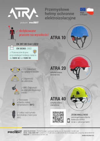
Wejdź na stronę
protekt.pl
Materiały Budowlane 02/2024, Okładka III (spis treści >>)


